
The Industrial Internet of Things (IIoT) is revolutionizing industrial plant operations by embedding advanced connectivity, data analytics, and automation into manufacturing processes. IIoT integrates a network of interconnected devices, sensors, and systems that collect, exchange, and analyze data in real-time, enabling unprecedented operational efficiency, productivity, and predictive maintenance. This digital transformation is turning traditional manufacturing into smart ecosystems, driving significant improvements and positioning industries to meet modern marketplace demands and future challenges. The following article describes the development process of an IoT product, providing insights into how these transformative technologies are created and implemented in industrial settings.
Why?
This project started with a request from a company for a controller that could remotely turn devices on and off and read temperature data. The challenge was that the controller needed to operate without Wi-Fi, which complicated the search for a suitable device due to various technical and economic constraints.
Remote control without Wi-Fi is technically possible, but it involves higher costs for hardware, infrastructure, and power consumption. Additionally, these solutions face limited market demand, regulatory hurdles, and integration challenges, making them less affordable compared to widely used Wi-Fi-based options. Wi-Fi remains cost-effective because it leverages existing infrastructure and benefits from economies of scale.
Non-Wi-Fi methods, such as cellular and satellite, are more expensive, require additional infrastructure, and consume more power, leading to higher complexity and costs. The limited market for these alternatives results in higher per-unit prices, making them less attractive. Given that existing devices do not meet the specific requirements, particularly in logging temperature information, we decided to develop a custom solution.
Project overview
To satiisfy the company’s requests we need to start from the techincal requirements:
- Remote control
- Two outputs
- Temperature log
The only viable connectivity solution for this project is the GSM cellular network, which allows us to use cost-effective devices that operate on GSM. This setup requires a SIM card and an internet plan, but it enables the microcontroller to read and write information via a GSM-enabled module, control relays, and read data from a temperature sensor. By leveraging the company’s existing website server, we can remotely manage the microcontroller through web calls, ensuring centralized and efficient control.
For the initial prototype, the GSM module will be used solely to retrieve status updates from the web server, simplifying the code logic and making it easier to maintain. This setup defines five time slots, each repeating every 24 hours, allowing the server to handle complex logic based on real-time data. Although this method requires frequent web calls, it offers straightforward maintenance and updates. In the future, we may store the time slots in the microcontroller’s ROM and manage timing internally to reduce server dependency.
Hardware
The selected microcontroller for this project is the Wemos D1 Mini, based on the ESP8266 architecture. This choice allows for easy management of various inputs and outputs with very low energy consumption. Additionally, the Wemos D1 Mini is compact and includes all necessary features at a highly competitive price. The GSM module chosen is the Sim800L, a relatively older device available at a very low cost. The only drawback of this module is its reliance on the GPRS network, which will be deprecated in the coming years. However, it still functions well in Italy for the time being.
For the temperature reading, we use a DS18B20 digital sensor. Cheap, accurate and easily integrable thanks to the OneWire protocol. In addition, we need relays with the appropriate interface circuit to control the devices. We also require a suitable voltage conversion from the 230V AC of the industrial plant to the 5V for the controller and the 4.2V for the Sim800L. The Sim800L requires at least 2A of current for the connectivity process, which can be challenging to manage for these devices.
flowchart LR
id0[(web server)]-.->|APIs|id8[GSM Module]<--->id1{T1}<--->id2[Microcrontroller]--->id3{States}--->id4([Output1])
id3--->id5([Output2])
id2<--->id6{T2}<--->id7[Temp sensor]
id6--->id8-.->|APIs|id0
id0<-->id9[Dashboard]o--oid10(User)
Software
The software development includes creating custom firmware to control the microcontroller and a website that allows users to manage, control, and schedule time slots.
Firmware
The firmware enables the Wemos D1 to periodically check the server, based on a predefined timer, for updated datetime, and the latest 24-hour schedule. A second timer triggers the push of temperature data. Additionally, an SMS can remotely force an immediate update. The firmware is designed to maintain reliability even during short-term power or network failures, with data retention for up to a month stored in the Wemos memory.
Webserver
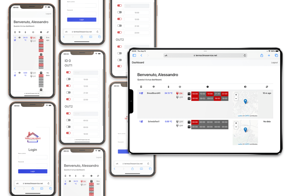
The web server is designed to provide users with an easy way to monitor the board’s status through a custom dashboard. Additionally, users can view and activate time slots, as well as set auxiliary information such as the board’s geographical location. This development involved creating both a user-friendly front-end and a backend capable of interacting with the board via custom APIs.
Prototype
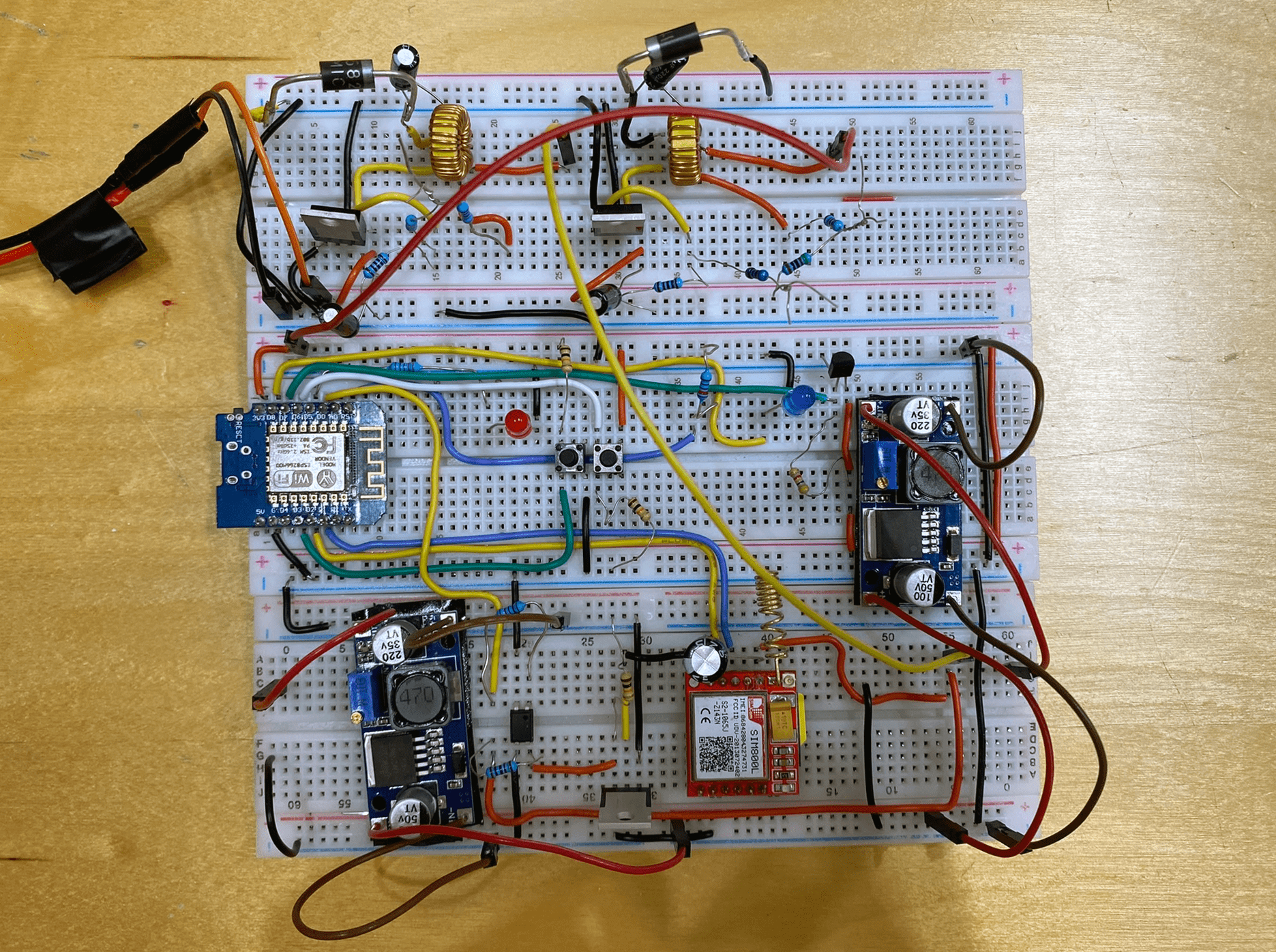
The prototyping phase of the project involved initially assembling the circuit on a breadboard to test and validate the components. This approach allowed for easy adjustments and troubleshooting as different sensors, microcontrollers, and modules were integrated. By using a breadboard, it is possible to experiment with various configurations and ensure that all components work together seamlessly before committing to a final design.
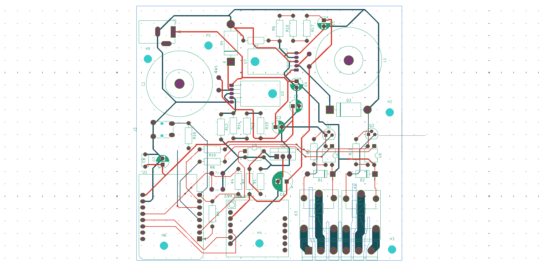
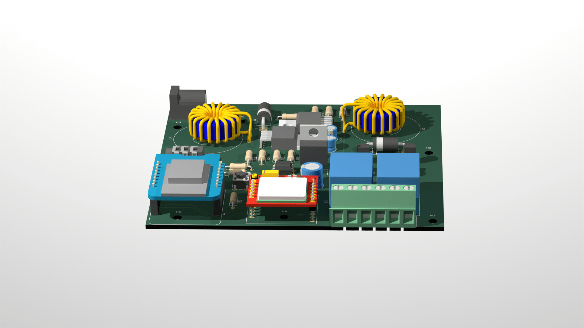
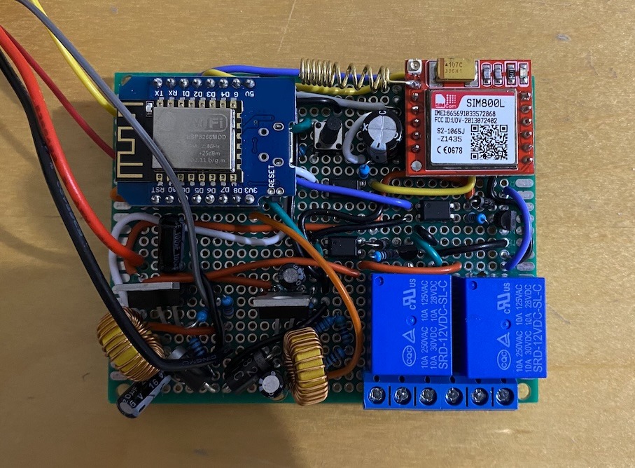
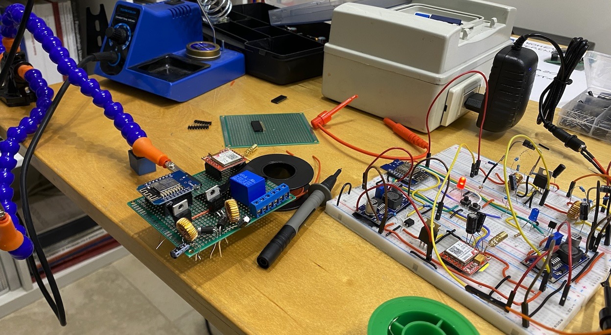
Once the breadboard prototype proved successful, the project moved to the next stage: designing a PCB (Printed Circuit Board) layout. The PCB was designed to accommodate through-hole (THT) components, ensuring a more durable and reliable assembly. This layout was then sent to a third-party manufacturer for production. The transition from a breadboard prototype to a custom PCB not only streamlined the circuit but also prepared the project for more extensive testing and eventual deployment.
Future improvements
Future developments involve transitioning to a PCB layout with Surface-Mount Technology (SMT) components, which will significantly reduce the size of the device and enhance its overall compactness. This miniaturization will not only make the device more efficient in terms of space but also pave the way for mass production, allowing for large-scale manufacturing at a lower cost. The shift to SMT components will improve the reliability and performance of the device by reducing the potential for mechanical failures associated with traditional through-hole components.
In addition to the PCB redesign, a durable and industrial-grade casing will be developed to protect the device in harsh environments. This casing will be engineered to meet the rigorous demands of industrial settings, providing resistance to dust, moisture, and other environmental factors. The design will also facilitate easy integration into existing electrical panels, ensuring that the device can be seamlessly incorporated into various industrial applications. These advancements will not only improve the functionality and resilience of the device but also make it more suitable for widespread deployment in industrial scenarios.